








- Architectural Control of Dynamic Vapor Phase Polymerization of Polypyrrole via Oxidant Infiltration Engineering
Jongyoon Kim# , Rizwan Khan# , and Jin-Heong Yim†

Division of Advanced Materials Engineering, Kongju National University, Budaedong 275, Seobuk-gu, Cheonan-si, Chungnam 31080, Korea
- 산화제 담지 엔지니어링을 통한 폴리피롤의 동적 기상 중합 설계제어
김종윤# · 리즈완칸# · 임진형†
공주대학교 공과대학 신소재공학부
Reproduction, stored in a retrieval system, or transmitted in any form of any part of this publication is permitted only by written permission from the Polymer Society of Korea.
This study presents a comparative evaluation of pressurization, ultrasonication, and vacuum pretreatments for Iron(III) p-toluenesulfonate (FTS) oxidant incorporation into mesoporous silica, highlighting their relative effectiveness in promoting oxidant infiltration. The oxidant-pretreated silica samples were subjected to polypyrrole (PPy) coating via dynamic vapor phase polymerization (D-VPP) under identical reaction conditions to systematically investigate variations in pore utilization and resulting structural development. Electrochemical measurements revealed that the silica–PPy composite prepared using pressurization pretreatment exhibited the highest specific capacitance (648.6 mF g-1) compared with those treated by ultrasonication (381.4 mF g-1) and vacuum methods (350.0 mF g-1). The enhanced capacitive performance is attributed to effective oxidant penetration into the pore channels during pressurization treatment, which enables higher PPy loading (10.1 wt%) and uniform growth within the mesoporous framework, thereby promoting more continuous electron transport pathways and improved electrolyte ion accessibility. These findings demonstrate that pretreatment conditions critically determine oxidant distribution and polymer growth inside the porous matrix.
본 연구는 메조기공 실리카 내로 Iron(III) p-toluenesulfonate(FTS) 산화제를 도입하기 위한 가압(pressurization), 초음파(ultrasonication), 진공(vacuum) 전처리 방법을 체계적으로 비교하여, 각 공정의 산화제 침투 효율과 그 효과를 정밀하게 평가하였다. 산화제로 전처리된 실리카는 동일한 반응 조건하에서 동적 기상 중합(dynamic vapor phase polymerization, D-VPP)을 이용하여 폴리피롤(PPy)로 코팅되었으며, 이를 통해 기공 활용도와 구조적 발달 양상의 차이를 규명하고자 하였다. 전기화학적 측정 결과, 가압 전처리를 적용한 실리카–PPy 복합체가 648.6 mF g-1의 가장 높은 비정전용량을 나타내어, 초음파 처리(381.4 mF g-1) 및 진공 처리(350.0 mF g-1) 시료 대비 현저한 성능 향상을 보였다. 이러한 성능 증가는 가압 전처리 과정에서 산화제가 기공 채널 내부로 효과적으로 침투함으로써, 더 높은 PPy 적재량 (10.1 wt%)과 메조기공 구조 전반에 걸친 균일한 고분자 성장을 유도하고, 그 결과 효율적인 전도 경로가 형성되었기 때문으로 해석된다. 본 연구 결과는 전처리 조건이 다공성 매트릭스 내부의 산화제 분포와 고분자 성장 거동을 결정적으로 제어함을 보여주며, 에너지 저장 응용을 위한 다공성 호스트 재료 내 전도성 고분자 도입 전략을 정밀하게 설계하는 데 유용한 설계 프로토콜을 제공한다.
In this work, we systematically compare pressurization, ultrasonication, and vacuum pretreatments for incorporating iron(III) p-toluenesulfonate into mesoporous silica and coating it with polypyrrole using dynamic vapor phase polymerization. The results demonstrate that pretreatment conditions critically control oxidant distribution, pore utilization, and polymer growth behavior. Pressurization enables the most efficient oxidant infiltration, resulting in higher PPy loading (10.1 wt%) and improved electrochemical behavior.
Keywords: vapor phase polymerization, polypyrrole, iron(III) p-toluenesulfonate, porous silica, pressure-assisted impregnation, electrochemical performance.
This research was supported by the National University Development Project by the Ministry of Education in 2025. And this research also was supported by the Basic Science Research Program through a National Research Foundation of Korea (NRF) grant funded by the Korean government (MSIT) (No. RS-2023-00221237 and No. RS-2024-00335799).
The authors declare that there is no conflict of interest.
Electroactive polymers or conductive polymers have been widely explored as electrodes for the application of electrochemical energy storage in the form of electrochemical capacitors because of their higher pseudocapacitance, redox reaction rate, and tunability.1,2 Of these polymers, polypyrrole (PPy) is considered more attractive because of its higher theoretical specific capacitance values, ease of synthesis, and relatively higher electronic conductivity.3,4 However, the utilization of PPy in the development of supercapacitors (SCs) still suffers from certain limitations in its inherent properties of poor cycle stability, volume expansion after cyclic charging and discharging operations, and less effective utilization of electroactive surface areas in the bulk polymer morphology.5
In order to address the given challenges, significant efforts have been devoted to nano-structuring PPy and integrating this with host materials capable of stabilizing the polymer and enhancing charge transport. Porous silica, carbon, metal oxides, and metal-organic frameworks have all been used as templates or supports for the spatial organization of conducting polymers.6,7 Silica represents an appealing host among various porous hosts due to its chemical stability combined with tunable pore structure and large surface area.8 Porous silica spatially confines conducting polymers when used as a template, which restricts excessive changes in volume, thereby stabilizing the polymer against mechanical deformation and improving the accessibility of electrolytes.9,10 Having said that, efficient infiltration of monomers and oxidants into the internal pore architecture remains a key challenge to be overcome for templated polymer growth.
Conventional liquid phase polymerization can lead to an inhomogeneous deposition of the PPy, as the diffusion of the monomers as well as the oxidant into the pores is not efficient.11-13 This results in the deposition of the polymers mostly on the outer surface of the porous substrate, while the available surface area inside remains largely unutilized. Vapor phase polymerization (VPP), a more efficient alternative, is used for the preparation of conducting polymer films.14,15 The process involves the use of an oxidant-coated substrate on which the vapor of the monomers is passed, thus ensuring a uniform diffusion of the vapor, which leads to the deposition of the polymers with significantly less agglomeration of the polymers as compared to the liquid phase process.
The combination of VPP and porous templates like silica has the potential to produce evenly distributed conducting polymer networks with a high surface area.16 A crucial factor for the success of VPP in a porous material is the effective and uniform distribution of the oxidative agent inside the pores. If the oxidative agent is confined to the exterior surface or to small areas in the material, polymerization will occur only in those areas. Thus, a major volume of the pores will not be utilized. Some methods that have been adopted to improve the infiltration of oxidative agents inside a porous material are ultrasonication, vacuum impregnation, and pressurization.17-19 In ultrasonication, the increase in mass transport is facilitated due to the formation of cavitation bubbles. Pressure-assisted infiltration has also been used, where a positive pressure is applied externally to further force the oxidant solution into the porous substrate. Each of these techniques has its own advantages and disadvantages, such that sonication can be beneficial in increasing infiltration while also introducing defects, vacuum impregnation is beneficial for pore filling while introducing problems of non-uniformities of oxidant distribution, and pressure-assisted techniques are beneficial for deeper penetration while requiring precise pressure adjustment to avoid pore collapse and non-uniformities of oxidant distribution. Moreover, there is limited research on the correlation between oxidant distribution followed by polymerization and its impact on electrochemical activity or SC performance. Whereas numerous studies have been made regarding VPP onto porous substrates,20-22 most literature deals with a single approach to infiltrate oxidant, without providing direct comparisons under identical conditions, which restricts mechanistic insight.
In this study, we systematically examined the role of various methods for introducing iron(III) p-toluenesulfonate (FTS) oxidants into porous silica template, followed by dynamic vapor phase polymerization (D-VPP) of PPy. In the D-VPP process, pyrrole (Py) monomers are delivered in the vapor phase and polymerize upon contact with the oxidant-coated substrate, enabling controlled PPy growth, improved infiltration into porous structures, and uniform coating under well-defined reaction conditions. By using sonication, pressure-assisted infiltration, and vacuum impregnation to infiltrate the internal pores with oxidants for D-VPP, we expected to examine the various roles and effects played by the methods on oxidant distribution, PPy structure, and, consequently, electrochemical performance. The findings offer a systematic basis for understanding and tailoring conducting polymer incorporation within porous host materials for energy storage applications.
Materials and Reagents. The mesoporous silica used in this study was SP2408HT (pore volume = 1.5 mL·g-1, surface area = 295 m2·g-1) purchased from Grace (USA). FTS from Sigma-Aldrich (USA) was used as the oxidant. Potassium hydroxide (KOH, ³99.9%, pellets), ethanol (99.9%) from Samchun Pure Chemical (Republic of Korea) was used as the solvent for preparing the oxidant solution. Py (99%) monomer was obtained from Acros (USA). Ultrasonic treatment was carried out using a POWERSONIC 410 unit (40 kHz), and pressure pretreatment was performed in an autoclave reactor (Hanwoole Engineering, Republic of Korea). Vacuum pretreatment was conducted using a TRP-12 vacuum pump and a vacuum desiccator. A 6 M KOH aqueous solution was used as the electrolyte.
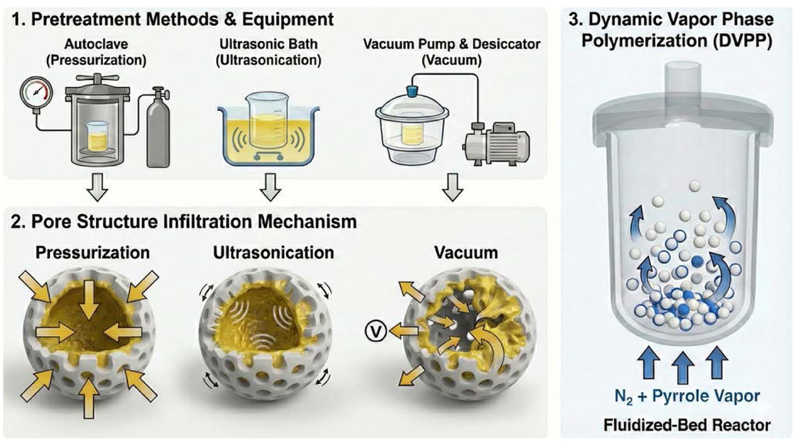
Silica Pretreatment Process. An FTS 10 wt% solution was prepared by dissolving 1.8 g of FTS in 18 g of ethanol (22.8 mL) in a beaker and stirring at 800 rpm for 10 min using a magnetic stirrer until the FTS was completely dissolved. Subsequently, 0.5 g of silica was added to 20 mL of the FTS solution and stirred for 12 h. The resulting mixture was then subjected to three different pretreatment methods. For the pressure-based pretreatment (pressurization), the autoclave reactor was operated at 10 bar for 1 h so that the oxidant solution was forced into the interior of the pores. For the ultrasound-based pretreatment (ultrasonication), the mixture was treated for 1 h in an ultrasonic cleaner (40 kHz), where cavitation and microstreaming promoted the penetration of the oxidant solution into the pores. For the vacuum‑assisted pretreatment (vacuum‑assisted infiltration), the sample was kept under vacuum at −0.1 MPa for 1 h in a vacuum desiccator, and the vacuum was then rapidly released so that the solution was drawn into the pores as the pressure returned to ambient. After each pretreatment, the samples were washed to remove residual FTS from the surface by mixing with ethanol and centrifuging at 3000 rpm for 3 min, repeated five times. The washed samples were then dried in a drying oven at 60 °C for 12 h to remove ethanol, yielding silica that was ready for subsequent PPy polymerization.
Polymerization of PPy Using D-VPP Process. D-VPP was carried out using a fluidized-bed reactor (FBR) setup. The porous oxidant-coated silica powder was placed on a porous distributor plate at the bottom of the reactor, beneath which an inverted glass funnel was installed. Nitrogen gas was introduced at the base of the reactor and rose through the porous plate to fluidize the powder and allow it to be exposed evenly to Py monomer vapor. During the course of polymerization, the monomer Py was kept in another container, which was connected to the nitrogen line, to permit the carrier gas to carry Py vapor into the reactor. The fluidized particles of silica were continuously exposed to the incoming Py vapor, which ensured efficient gas–solid contact and uniform deposition of PPy on the surface as well as within the pores of the silica particles. The fluidized bed offers greater advantages over the static VPP process, which suffers from low mass transfer and clogging during polymerization within the pores.
For comparison, all samples were polymerized under identical VPP conditions. The samples were placed in the fluidized-bed reactor and exposed to nitrogen-carried Py vapor, preheated to 25 °C, at a flow rate of 10 cc min-1 for 20 min. The resulting PPy–silica composites obtained under different pretreatment conditions were denoted as silica–PPy–p (pressure-treated), silica–PPy–u (ultrasonically treated), and silica–PPy–v (vacuum-treated). Pristine porous silica without pretreatment or polymerization was used as a control.
Electrochemical Characterization. The composition of the electrodes is a mixture of silica-PPy with carbon black (CB) as a conductive additive and poly-vinylidene fluoride (PVDF) as a binder. The above materials are mixed in a composition of 80% active materials, to 10% of CB, and 10% of PVDF. To prepare this mixture well, 2 mL of N-methyl-2-pyrrolidone (NMP) is to be added to it. The mixture is then magnetically stirred at 800 rpm for 10 minutes. This is further processed in an ultrasonic bath (40 kHz) at 30 minutes. This step should provide a well-prepared mixture or slurry. This mixture is evenly deposited as a layer on nickel foam with a radius of 0.5 cm, acting as a current collector. The electrodes are kept totally dry at 80 °C for 12 h. For making SC, two identical electrodes are placed in split cells separated by Whatman filter paper. The cells are pressed between metal plates with spring support to provide proper electrical contacts.
The electrochemical measurement was performed with a potentiostat SP-150 (BioLogic, France) and a 6 M KOH aqueous solution. Electrochemical property tests of the samples included cyclic voltammetry (CV), galvanostatic charge/discharge (GCD), and electrochemical impedance spectroscopy (EIS). For CV tests, the potential range was 0 to 0.8 V, and the GCD tests also included a range from 0 to 0.8 V. EIS tests included the application of an AC current of 100 µA at a sweep range from 100 kHz to 0.1 Hz. The cycle stability and coulombic efficiency for 1–10000 cycles were measured through the charging and discharging test.
Morphological and Chemical Characterization. The morphology of the synthesized PPy composites was examined using transmission electron microscopy (TEM; JEM-F200, JEOL, Japan, operated at 200 kV) and field-emission scanning electron microscopy (FE-SEM; MIRA LMH, TESCAN, Czech Republic, operated at 20 kV with a beam current of 7 µA). Elemental composition was analyzed by energy-dispersive X-ray spectroscopy (EDS; XFlash Detector 5010, Bruker, USA). Functional groups were identified using Fourier transform infrared spectroscopy (FTIR; Spectrum Two, PerkinElmer, USA) recorded in the range of 500–4000 cm-1 using the KBr pellet method. Chemical bonding states were investigated by X-ray photoelectron spectroscopy (XPS; K-Alpha, Thermo Fisher Scientific, USA). Thermogravimetric analysis (TGA; Pyris 1 TGA, PerkinElmer, USA) was conducted under a nitrogen atmosphere over a temperature range of 100–900 °C to evaluate mass changes and thermal stability. The pore structure and surface area were characterized by Brunauer–Emmett–Teller (BET) analysis using N₂ adsorption–desorption isotherms measured at 77 K (ASAP 2020, Micromeritics, USA).
Synthesis of Composites. Several techniques for introducing oxidants before polymerization were investigated in order to demonstrate the effects of oxidant distribution during the VPP of PPy inside a porous silica matrix. In these methods, sonication, pressure-assisted infiltration, and vacuum impregnation were employed to introduce the oxidant into the internal pores of the silica matrix prior to PPy polymerization using D-VPP (Figure 1). The methods were selected because they serve to create diverse mass transport processes. In sonication, oxidants are introduced into the matrix using microstreaming cavitation. In vacuum impregnation, introduction into the matrix is facilitated by the removal of air bubbles. In pressure-assisted infiltration, the oxidants are forced into the matrix. As a result, each approach is expected to generate different oxidant distributions within the silica matrix, which in turn strongly affects PPy nucleation, growth location, and coating uniformity during D-VPP. In D-VPP, Py vapor diffuses toward oxidant-impregnated substrates, where oxidative polymerization is initiated locally, resulting in a controlled buildup of PPy that extends into porous frameworks and yields conformal coatings under regulated processing conditions. We hypothesize that variations in oxidant accessibility within the pores lead to significant differences in polymer morphology, pore coverage, and interfacial contact between PPy and silica. By comparing the structural and electrochemical properties of the resulting composites, the role of oxidant infiltration in governing the internal architecture and performance of PPy–silica electrodes can be clearly established.
SEM Analysis. SEM analysis was performed to investigate the surface morphology of pristine silica and silica–PPy–p, silica–PPy–u, and silica–PPy–v composites after oxidant pretreatment followed by D-VPP of PPy. Accordingly, Figure 2(a)-(c) depicts that the surface of pristine silica is rather smooth and homogeneous. After PPy polymerization, all silica–PPy samples exhibit a significant increase in the roughness of their surface morphology, thus confirming the structural changes. No major morphological differences are clearly distinguishable at the SEM scale among the three types of silica–PPy samples, though subtle variations might be remarked on in their surfaces. These subtle differences are manifested in various ways, such as through the extent of surface roughness and polymer agglomeration. Of note, silica–PPy–p has a relatively more uniform and porous-like morphology, indicating that more homogeneous growth of PPy occurred (Figure 2(d)-(f)). In contrast, silica–PPy–u and silica–PPy–v have slightly higher extents of agglomeration and less homogeneous features (Figure 2(g)-(i)). In general, the SEM observations revealed that different oxidant pretreatment approaches yielded minor modifications in the surface morphology of PPy while maintaining similar external features.
EDS analysis was carried out to identify the elemental composition of pristine silica and PPy-coated composites. Indeed, as shown in Table 1, the pristine silica is dominated by the elements Si and O, while C, N, S, and Fe could only be detected in trace quantities. In contrast, all pretreated samples silica–PPy–p, silica–PPy–u, and silica–PPy–v exhibit a noticeable increase in nitrogen content, which serves as a key indicator of successful PPy incorporation, as nitrogen is a characteristic element of PPy. Rather than emphasizing differences among the samples, Table 1 confirms that the application of any pretreatment method effectively enables PPy formation, imparting the fundamental compositional features of PPy–silica composites to all samples.
TEM-EDS Analysis. The microstructural features of pristine silica and the pressure-treated PPy composite (silica–PPy–p) were further examined by TEM and TEM–EDS analysis, as shown in Figure 3. The pristine silica (Figure 3(a) and (b)) has a fairly uniform contrast with loosely packed domains at a nanoscale level. This indicates that it has an amorphous porous silica structure. The TEM-EDS elemental map of the pristine silica (Figure 3(c)) shows very small amount of C, N, S, and Fe. The TEM images of silica-PPy-p sample showed variation in contrast, which is more prominent, and there exist dark areas around the silica domains (Figure 3(d) and (e)). The dark areas indicate the development of a thin polymer film on the surface of the silica domains as well as within the pores.23
Figure 3(f) shows the TEM–EDS mapping of silica–PPy–p, indicates a homogeneous spatial distribution of C and N, characteristic elements of PPy, along with S and Fe originating from the dopant species. These elements are uniformly dispersed across the silica framework, confirming the successful incorporation of PPy in it and further indicating that pressure-assisted pretreatment allows for effective oxidant infiltration into the porous network, hence allowing for controlled PPy growth inside the silica structure rather than localized accumulation on the surface. These results offer strong evidence that the presence of pressure-assisted pretreatment leads to efficient oxidant penetration into the silica matrix, favoring the growth of PPy through the nucleation process in the vapor-phase polymerization.
FTIR and XPS Analysis. Figure 4 shows the FTIR and XPS results employed to interpret the chemical composition of pristine silica as well as the surface interaction of PPy coatings on pristine silica. The FTIR spectra of pristine silica (Figure 4(a)) show characteristic absorption peaks at ~1630 cm-1 due to the bending vibration of Si–OH and at ~805 cm-1 due to the bending of the Si–O–Si vibration of silica.23,24 However, all PPy-coated samples (silica-PPy-p, silica-PPy-u, and silica-PPy-v) display the new appearance of the bands at 1560 cm-1 and 740 cm-1, a PPy ring C=C bond vibration mode, and a PPy ring C-H out-of-phase bending, respectively.25 The observation of these new absorption bands indicates successful PPy growth on pristine silica templates. Moreover, the result indicates that PPy synthesis occurs regardless of the sample pretreatment process.
The XPS analysis further assists in understanding the surface chemical states and interfacial composition. The high-resolution Si 2p spectrum of pristine silica (Figure 4(b)) can be differentiated into Si-O-Si and Si-OH bonds, representing the siloxane bonds and surface hydroxyl groups.26 The N 1s and Fe 2p spectra of pristine silica (Figure 4(c) and (d)) reveal no nitrogen presence. For the silica-PPy-p composite (Figure 4(e)), there is a minor broadening and emergence of new peaks in the Si 2p spectrum, which are ascribed to modified Si-O bonds. This is ascertained to be an indication of interfacial reactions occurring at the interface between the silica surface and the deposited PPy layer. Conversely, in the case of the silica-PPy-p composite (Figure 4(f)), well-resolved N 1s peaks are identified and assigned to neutral N-H bonds and positively charged N+ bonds, which are representative of doped polymeric chains in PPy.27 Inclusion of Fe ions within the chains of PPy is evident from the Fe 2p spectra (Figure 4(g)), which show the existence of Fe ions only after the polymerization with Fe ions.28 This Fe ion confirms the incorporation of FTS oxidant into silica matrix.
The FTIR and XPS spectra together support the successful incorporation of oxidant and PPy formation which resulting in intimate interfacial contact with the silica framework. Preservation of the silica-related features with the emergence of PPy-specific signals indicates that PPy is being conformally deposited onto the silica without the disruption of the structure, while the presence of doped nitrogen species supports the formation of an electrochemically active PPy phase.
BET and TGA Analysis. Changes in the silica pore structure induced by the incorporation of PPy were clearly identified by nitrogen adsorption–desorption measurements using BET analysis. In Figure 5(a), silica, silica-PPy-p, silica-PPy-u, and silica-PPy-v all exhibit a typical type IV isotherm with an H4 hysteresis loop characteristic of mesoporous silica.29 In all silica-PPy samples, the overall adsorption–desorption volume decreases compared with silica, which can be interpreted as a result of PPy partially occupying the pore walls and internal spaces, thereby restricting nitrogen adsorption.30 Corresponding differences are also observed in the pore-size distribution curves shown in Figure 5(b).
While pristine silica shows the largest pore volume, all silica–PPy samples exhibit reduced pore volumes over the measured range, suggesting that some of the pores were partially occupied or coated by PPy. BET analysis results are summarized in Table 2. Pristine silica exhibited a specific surface area of 280.94 m2·g-1 and a pore volume of 1.50 cm3·g-1. Compared with pristine silica, all three silica–PPy samples showed reduced specific surface area and pore volume. The decreases in specific surface area were 47.56, 35.02, and 39.18 m2·g-1 for silica–PPy–p, silica–PPy–u, and silica–PPy–v, respectively, while the corresponding decreases in pore volume were 0.21, 0.17, and 0.20 cm3·g-1. Among the three pretreated samples, silica–PPy–p showed the largest decreases in both specific surface area and pore volume, indicating the greatest reduction in accessible pore structure after PPy incorporation. In contrast, the average pore size remained within a similar range (15.4–15.9 nm), which may be attributed to the relatively broad pore-size distribution of the amorphous silica framework. This suggests that PPy was introduced mainly through partial pore filling or pore-wall coating rather than complete pore blockage or collapse of the silica framework.
With the changes in surface area and pore structure established from the BET results, the TGA analysis, as shown in Figure 6(a,b), was utilized in order to determine the quantity variation of the polymers as well as the oxidant added in the samples. Silica shows only a very slight weight loss over the entire temperature range, reflecting the thermal stability of a material that possesses only the pore framework.31 In contrast, the three pretreated samples (silica–PPy–p, silica–PPy–u, silica–PPy–v) commonly exhibit weight loss due to the thermal decomposition of the polymer and residual oxidant components. This result indicates that PPy has been introduced into the silica structure regardless of whether pretreatment is applied. Figure 6(b) shows the differences in mass fraction at 700 °C relative to the initial sample mass, and the inset graph presents the differences in mass fraction for each pretreatment method compared with silica. Silica–PPy–p (10.1 wt%) exhibits a higher weight loss ratio than silica–PPy–u (7.5 wt%) and silica–PPy–v (8.3 wt%), indicating that a larger amount of PPy is introduced into the pores. This trend is consistent with the BET results, where the decreases in specific surface area and pore volume follow a similar order, supporting that larger reductions in accessible pore structure are associated with higher PPy loading within the mesoporous silica. Based on the combined results from BET and TGA analyses, it is confirmed that the pressure-based method acts as the most effective means to improve the accessibility and efficiency of polymer loading within the pores.
Electrochemical Performance. Next, the electrochemical properties of the silica–PPy composites prepared by different pretreatment methods were measured and compared in two electrode system. Various techniques, including CV, GCD, EIS, Ragone plots, and long-term charge–discharge tests, were carried out on the obtained composites. The CV parameters measured the highest current-potential region for silica-PPy-p among the four samples (Figure 7(a)). This indicated superior charge storage capability. Silica−PPy−u and silica−PPy−v showed a similar CV area, while pristine silica exhibited the smallest area, indicating the lowest electrochemical activity. This is consistent with the idea that the amount of PPy introduced into the pores during the pretreatment step influences the CV characteristics directly. The same performance order was demonstrated by GCD analysis (Figure 7(b)). Silica–PPy–p exhibited the longest discharge time (51.9 s) and the highest specific capacitance (648.6 mF g-1) at 10 mA/g, showing the best capacitive performance among the four samples. Silica–PPy–u (381.4 mF·g-1 at 10 mA·g-1) and silica–PPy–v (350.0 mF·g-1 at 10 mA·g-1) also resulted in enhanced capacitance with respect to the pristine silica counterpart (211.0 mF·g-1); however, the loading effect driven by the pressure-based pretreatment was not attained. Because PPy is generally insoluble and infusible, and because conventional GPC-based molecular-weight characterization is often challenging for conjugated polymers, direct molecular-weight determination was not feasible for the pore-confined PPy formed in this system.32,33 Accordingly, the superior electrochemical performance of silica–PPy–p is discussed here mainly in terms of relative PPy incorporation and pore utilization, as inferred from the BET, TGA, and electrochemical results. In the EIS analysis, silica–PPy–p showed the steepest slope in the Nyquist plot, indicating the lowest diffusion resistance (Figure 7(c)). The coulombic efficiency remains relatively equal for all samples irrespective of the pretreatment process, and this suggests equal long-life cycles (Figure 7(d)). In addition to this, by analyzing the GCD features of silica-PPy-p for cycles 101-105, 1001-1005, 5001-5005, and 9001-9005, it could be seen that there was no deviation in the voltage-time relationship (inset Figure 7(d)). Thus, from all the electrochemical tests, it could be concluded and supported that the pressure-based pretreatment technique exhibits the highest ability to insert PPy into the pores in the silica matrix to deliver greater storage capabilities, ion mobility, power capability, and cyclability. This could be justified from the above studies by taking into account the structural and chemical features identified by TEM, EDS, FTIR/XPS, and BET/TGA studies.

|
Figure 1 Schematic representation of the preparation process for different silica-PPy composites under different pretreatment conditions. |

|
Figure 2 (a–c) SEM images of pristine silica at different magnifications; (d–f) SEM images of silica–PPy-p at different magnifications; (g– i) SEM images of silica–PPy-u at different magnifications; (j–l) SEM images of silica–PPy-v at different magnifications. |

|
Figure 3 (a, b) TEM images of silica recorded at different magnifications; (c) TEM-EDS elemental mapping of silica showing the distributions of C, N, S, and Fe; (d, e) TEM images of silica–PPy-p at different magnifications; and (f) TEM-EDS elemental mapping of silica– PPy-p (C, N, S, and Fe). Only these four elements are presented to clearly highlight the compositional differences between pristine silica and the PPy-modified silica sample. |

|
Figure 4 (a) FTIR spectra of silica samples prepared under different pretreatment conditions; high resolution XPS spectra of silica; (b) Si 2p; (c) N 1s; (d) Fe 2p; high resolution XPS spectra of silica-PPy-p; (e) Si 2p; (f) N 1s; (g) Fe 2p. |

|
Figure 5 (a) BET analysis of nitrogen adsorption-desorption isotherm; (b) corresponding pore-size distribution curves of silica, silica–PPy–p, silica–PPy–u, and silica–PPy–v. |

|
Figure 6 (a) Weight-loss profiles from TGA analysis of silica and all silica-PPy composites under N2 atmosphere with heating rate of 10 °C/ min; (b) wt. loss % of all samples; inset shows net wt. loss % of all samples. |

|
Figure 7 Electrochemical performance of silica, silica–PPy-p, silica–PPy-u, and silica–PPy-v evaluated in a two-electrode configuration: (a) CV curves; (b) GCD profiles; (c) EIS Nyquist plots; (d) cycling stability of all samples (inset representative GCD curves at selected cycle numbers). |
|
Table 1 Elemental Composition (wt%) of Silica-based Materials Before and After Vapor-polymerization, Obtained from SEM-EDS Analysis |

|
Table 2 Comparison of Specific Surface Area, Pore Volume, and Pore Size of Silica, Silica–PPy-p, Silica–PPy-u, and Silica–PPy-v Obtained from BET Analysis |

aSurface area calculated by the Brunauer-Emmett-Teller (BET) method from N2 adsorption isotherms in the range of p/p0 = 0.05-0.30; bTotal pore volume calculated from the N2 adsorption isotherm data at p/p0 = 0.99; cPore size calculated by the Barrett-Joyner-Halenda (BJH) method. |
In this study, pressure, ultrasonic, and vacuum pretreatments were applied to mesoporous silica to compare oxidant penetration and PPy polymerization behavior. PPy incorporation was confirmed for all pretreated samples, and among them, the pressure-based pretreatment led to the greatest penetration of oxidant into the pores and the highest level of PPy formation. Consequently, silica–PPy–p exhibited the most pronounced structural changes and showed the highest specific capacitance, superior ion transport properties, and stable charge–discharge behavior in electrochemical evaluations. This work verifies that the pretreatment process is a key factor in improving the structure and electrochemical properties of silica-PPy composites, among which the pressure pretreatment is the most efficient one. The relation between the pretreatment process and the in-pore inductive polymerization process discussed above will set up a new guide for the preparation of electrodes based on mesoporous materials, which can be adopted as a highly efficient strategy for the fabrication of high-performance, long-cycle lifetime SCs in the future.
- 1. Gharahcheshmeh, M. H.; Chowdhury, K. Fabrication Methods, Pseudocapacitance Characteristics, and Integration of Conjugated Conducting Polymers in Electrochemical Energy Storage Devices. Energy Adv. 2024, 3, 2668-2703.
-

- 2. Suriyakumar, S.; Bhardwaj, P.; Grace, A. N.; Stephan, A. M. Role of Polymers in Enhancing the Performance of Electrochemical Supercapacitors: A Review. Batteries Supercaps 2021, 4, 571-584.
-
- 3. Liu, Y.; Wu, F. Synthesis and Application of Polypyrrole Nanofibers: A Review. Nanoscale Adv. 2023, 5, 3606-3618.
-
- 4. Huang, Y.; Li, H.; Wang, Z.; Zhu, M.; Pei, Z.; Xue, Q.; Huang, Y.; Zhi, C. Nanostructured Polypyrrole as a Flexible Electrode Material of Supercapacitor. Nano Energy 2016, 22, 422-438.
-
- 5. Song, Y.; Liu, T.-Y.; Xu, X.-X.; Feng, D.-Y.; Li, Y.; Liu, X.-X. Pushing the Cycling Stability Limit of Polypyrrole for Supercapacitors. Adv. Funct. Mater. 2015, 25, 4626-4632.
-
- 6. Zhou, Z.; Yu, F.; Ma, J. Nanoconfinement Engineering for Enhanced Adsorption of Carbon Materials, Metal–organic Frameworks, Mesoporous Silica, MXenes and Porous Organic Polymers: A Review. Environ. Chem. Lett. 2022, 20, 563-595.
-
- 7. Zhang, S.; Chen, L.; Zhou, S.; Zhao, D.; Wu, L. Facile Synthesis of Hierarchically Ordered Porous Carbon via In Situ Self-assembly of Colloidal Polymer and Silica Spheres and Its Use as a Catalyst Support. Chem. Mater. 2010, 22, 3433-3440.
-
- 8. Kankala, R. K.; Han, Y.-H.; Na, J.; Lee, C.-H.; Sun, Z.; Wang, S.-B.; Kimura, T.; Ok, Y. S.; Yamauchi, Y.; Chen, A.-Z.; Wu, K. C.-W. Nanoarchitectured Structure and Surface Biofunctionality of Mesoporous Silica Nanoparticles. Adv. Mater. 2020, 32, 1907035.
-
- 9. Luo, H.; Kaneti, Y. V.; Ai, Y.; Wu, Y.; Wei, F.; Fu, J.; Cheng, J.; Jing, C.; Yuliarto, B.; Eguchi, M.; Na, J.; Yamauchi, Y.; Liu, S. Nanoarchitectured Porous Conducting Polymers: From Controlled Synthesis to Advanced Applications. Adv. Mater. 2021, 33, 2007318.
-
- 10. Li, B.; Shu, D.; Wang, R.; Zhai, L.; Chai, Y.; Lan, Y.; Cao, H.; Zou, C. Polyethylene Glycol/silica (PEG@SiO2) Composite Inspired by the Synthesis of Mesoporous Materials as Shape-stabilized Phase Change Material for Energy Storage. Renewable Energy 2020, 145, 84-92.
-
- 11. Wong, Y. C.; Wong, Y. H.; Ang, B. C.; Baharuddin, A. A.; Haseeb, A. S. M. A. Effects of Polymerization Oxidants on the Fabrication of Electrospun PPy/WO3 Composites. J. Mater. Sci.: Mater. Electron. 2023, 34, 33.
-
- 12. Qian, J.; Zhang, X.; Jia, Y.; Xu, H.; Pan, B. Oxidative Polymerization in Water Treatment: Chemical Fundamentals and Future Perspectives. Environ. Sci. Technol. 2025, 59, 1060-1079.
-
- 13. Sui, C.; Tan, R.; Liu, Z.; Li, X.; Xu, W. Smart Chemical Oxidative Polymerization Strategy to Construct Au@PPy Core–shell Nanoparticles for Cancer Diagnosis and Imaging-guided Photothermal Therapy. Bioconjugate Chem. 2023, 34, 257-268.
-
- 14. Oaki, Y.; Sato, K. Nanoarchitectonics for Conductive Polymers Using Solid and Vapor Phases. Nanoscale Adv. 2022, 4, 2773-2781.
-
- 15. Hanif, Z.; Tariq, M. Z.; Khan, Z. A.; La, M.; Choi, D.; Park, S. J. Polypyrrole-coated Nanocellulose for Solar Steam Generation: A Multi-surface Photothermal Ink with Antibacterial and Antifouling Properties. Carbohydr. Polym. 2022, 292, 119701.
-
- 16. del Valle, M. A.; Gacitúa, M. A.; Hernández, F.; Luengo, M.; Hernández, L. A. Nanostructured Conducting Polymers and Their Applications in Energy Storage Devices. Polymers 2023, 15, 1450.
-
- 17. Rahy, A.; Hong, S. J.; Yang, K. S.; Bunker, C.; Nadagouda, M. N.; Yang, D. J. Influence of Poly(ethylene glycol) and Oleylamine on the Formation of Nano- to Micron-size Spherical SiO2 Particles. Key Eng. Mater. 2012, 521, 163-169.
-
- 18. Ellerbrock, R.; Stein, M.; Schaller, J. Comparing Amorphous Silica, Short-range-ordered Silicates and Silicic Acid Species by FTIR. Sci. Rep. 2022, 12, 11708.
-
- 19. Liyanage, C. D.; Kumar, H.; Perera, I.; Abeykoon, P. G.; Chen, F.; Joya, J. S.; Suib, S. L.; Adamson, D. H. Synthesis of Graphene Oxide: Effect of Sonication During Oxidation. Carbon 2024, 223, 119047.
-
- 20. Kim, J.; Sohn, D.; Sung, Y.; Kim, E.-R. Fabrication and Characterization of Conductive Polypyrrole Thin Film Prepared by In Situ Vapor-phase Polymerization. Synth. Met. 2003, 132, 309-313.
-
- 21. Zhu, X.; Han, X.; Guo, R.; Yuan, P.; Dang, L.; Liu, Z.; Lei, Z. Vapor-phase Polymerization of Fibrous PEDOT on Carbon Fibers Film for Fast Pseudocapacitive Energy Storage. Appl. Surf. Sci. 2022, 597, 153684.
-
- 22. Karki, S.; Ingole, P. G. Development of Polymer-based High-performance Thin-film Nanocomposite Nanofiltration Membranes by Vapor-phase Interfacial Polymerization for Heavy Metal Ion Removal. Chem. Eng. J. 2022, 446, 137303.
-
- 23. Li, Z.; Zhang, S.; Tao, J.; Zhang, H.; Hu, S.; Liu, Q.; Jiao, J. Mesoporous Silica@polypyrrole and Its Epoxy Composites with Ultra-broadband Electromagnetic Wave Absorption Properties. Chem. Eng. J. 2024, 491, 152051.
-
- 24. Petreanu, I.; Niculescu, V.-C.; Enache, S.; Iacob, C.; Teodorescu, M. Structural Characterization of Silica and Amino-silica Nanoparticles by FTIR and Raman Spectroscopy. Anal. Lett. 2023, 56, 390-403.
-
- 25. Mahalingam, V.; Sivaraju, M.; Kumar, G. S.; Lalithambigai, K.; Priyan, S. R.; Alam, M. M. Synergistic Effect of Silica/polypyrrole Nanocomposites Synthesized by Hydrothermal Method Using Rice Husk as a Silica Source for Corrosion Protection. Mater. Chem. Phys. 2024, 313, 128752.
-
- 26. Zhai, L.; Hou, C.; Sun, H.; Qu, Y.; Hou, J.; Lu, H.; Wu, J.; Wang, B.; Ma, Y.; Guo, X. Polypyrrole In Situ Coated SiO as Anode Material for Lithium-ion Batteries with Excellent Cyclic Performance. J. Energy Storage 2024, 97, 112715.
-
- 27. Ding, C.; Qian, X.; Yu, G.; An, X. Dopant effect and Characterization of Polypyrrole–cellulose Composites Prepared by In Situ Polymerization. Cellulose 2010, 17, 1067-1077.
-
- 28. Yamashita, T.; Hayes, P. Analysis of XPS Spectra of Fe2+ and Fe3+ Ions in Oxide Materials. Appl. Surf. Sci. 2008, 254, 2441-2449.
-
- 29. Baldovino-Medrano, V. G.; Niño-Celis, V.; Isaacs Giraldo, R. Systematic Analysis of Nitrogen Adsorption–desorption Isotherms for Microporous–mesoporous Amorphous Aluminosilicates Using Classical Methods. J. Chem. Eng. Data 2023, 68, 2512-2528.
-
- 30. Esparza, J. M.; Ojeda, M. L.; Campero, A.; Hernández, G.; Felipe, C.; Asomoza, M.; Cordero, S.; Kornhauser, I.; Rojas, F. Development and Sorption Characterization of Model Mesoporous and Microporous Silica Adsorbents. J. Mol. Catal. A: Chem. 2005, 228, 97-110.
-
- 31. Almaghrabi, M.; Alqurshi, A.; Jadhav, S. A.; Mazzacuva, F.; Cilibrizzi, A.; Raimi-Abraham, B.; Royall, P. G. Evaluating Thermogravimetric Analysis for the Measurement of Drug Loading in Mesoporous Silica Nanoparticles. Thermochim. Acta 2023, 730, 179616.
-
- 32. Fair, R. A.; Xie, R.; Lee, Y.; Colby, R. H.; Gomez, E. D. Molecular Weight Characterization of Conjugated Polymers through Gel Permeation Chromatography and Static Light Scattering. ACS Appl. Polym. Mater. 2021, 3, 4572-4578.
-
- 33. Wang, L.-X.; Li, X.-G.; Yang, Y.-L. Preparation, Properties and Applications of Polypyrroles. React. Funct. Polym. 2001, 47, 125-139.
-

- Polymer(Korea) 폴리머
- Frequency : Bimonthly(odd)
ISSN 2234-8077(Online)
Abbr. Polym. Korea - 2025 Impact Factor : 1.0
- Indexed in SCIE
 This Article
-
2026; 50(4): 513-523
Published online Jul 25, 2026
- 10.7317/pk.2026.50.4.513
- Received on Jan 22, 2026
- Revised on Apr 15, 2026
- Accepted on Apr 16, 2026
Services
- Full Text PDF
- Abstract
- ToC
- Acknowledgements
- Conflict of Interest
Introduction
Experimental
Results and Discussions
Conclusion
- References
Shared
Correspondence to
- Jin-Heong Yim
-
Division of Advanced Materials Engineering, Kongju National University, Budaedong 275, Seobuk-gu, Cheonan-si, Chungnam 31080, Korea
- E-mail: jhyim@kongju.ac.kr
- ORCID:
0000-0002-3557-9564
 Copyright(c) The Polymer Society of Korea. All right reserved.
Hyecheon Building(Room 601), #354, Gangnam-Daero, Gangnam-Gu, Seoul 06242, Korea
TEL : 82-2-568-3860, 561-5203, 569-3860 FAX : 82-2553-6938 E-mail: polymer@polymer.or.kr